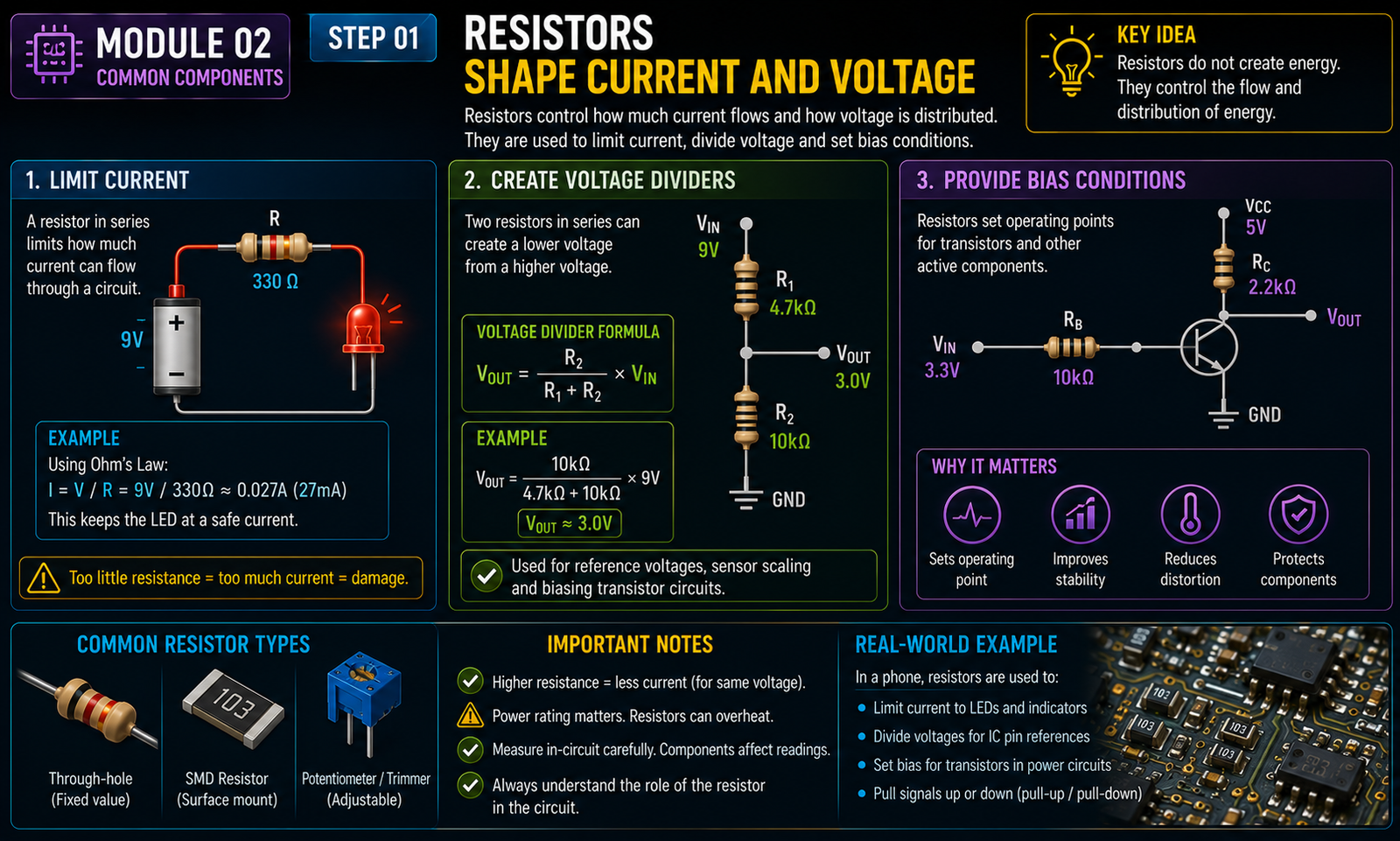
Resistors shape current and voltage
Resistors can limit current, create voltage dividers and provide bias conditions.
100% FREE ELECTRONICS COURSE • MODULE 02 OF 8
Learn the purpose and behavior of resistors, capacitors, diodes, LEDs, inductors, connectors, fuses and other common components you will encounter on electronic boards.
Learn the purpose and behavior of resistors, capacitors, diodes, LEDs, inductors, connectors, fuses and other common components you will encounter on electronic boards.
By the end of this module on common electronic components, you should be able to explain the key concept in your own words, identify when it is useful in repair reasoning, recognize its limitations, and describe a safe beginner-level way to apply it to low-voltage electronics.
Repair becomes easier to understand when you stop seeing a device as a collection of mysterious parts and begin seeing it as a system that moves energy and signals through connected components. Electronics fundamentals do not turn a beginner into a board-level specialist overnight, and they should not be used as an excuse to probe an unfamiliar circuit blindly. Their value is that they give you a language for asking better questions. Instead of saying the board is dead, you can ask whether low-voltage power is reaching a region, whether a connection is continuous, whether a fuse is open, whether a component is expected to conduct in one direction, or whether a measurement is meaningful for the state of the device.
This course focuses on low-voltage electronics found in phones, laptops and similar devices. It does not teach work on household mains wiring, power supplies connected to dangerous mains voltage, CRT equipment, microwave ovens or other high-energy systems. Even low-voltage devices can contain lithium-ion batteries capable of delivering high current, so damaged, swollen, punctured or overheating batteries require appropriate professional handling.
A multimeter reading is useful only when it answers a defined question. Before touching a probe to a circuit, write down what you want to learn. Are you checking whether two points are connected? Are you checking whether a low-voltage supply is present? Are you comparing a suspect path with a known-good reference? The meter mode, reference point and device power state all depend on that question.
Board layouts, connector pinouts, test points and expected measurements vary between models and revisions. Generic electronics knowledge helps you understand what a resistor or voltage rail is, but it does not tell you the correct value at every point on every device. When a physical procedure or measurement depends on an exact location, use reliable service documentation when appropriate.
Good electronics troubleshooting is evidence-driven. Photograph the board when helpful, write down meter mode and measured value, note whether the device was powered or unpowered, and record the reference point used. This prevents the common beginner problem of remembering a reading without remembering how it was obtained.
A probe tip can slip. A metal tool can bridge adjacent contacts. A connector can be damaged by excessive force. Work with good lighting, stable hand support and appropriate probe tips. When possible, make measurements at accessible test points rather than balancing a probe on a tiny component.
Finding continuity does not prove that a circuit will function under load. Finding no continuity does not automatically mean a broken connection if the circuit contains components that block the meter's test signal. Every measurement has limitations.
If you replace, reconnect or clean anything, return to the original symptom and repeat relevant functional tests. Electronics repair is complete when the behavior that justified the intervention is resolved and nearby functions still operate correctly.
Resistors can limit current, create voltage dividers and provide bias conditions.
Capacitors support filtering, timing and power stability.
Diodes often conduct differently by polarity. Protection devices can clamp abnormal voltages or interrupt fault current.
Create a hypothetical low-voltage repair case and write a measurement plan before touching any device. State the symptom, the exact question you want the measurement to answer, the meter mode you would choose, whether the circuit should be powered or unpowered, the reference point, the expected type of result and the action you would take for each possible outcome. Then list at least two reasons why the result could be misleading. This exercise teaches you to treat the meter as a tool for testing a hypothesis instead of as a magic detector.
Create a hypothetical low-voltage repair case and write a measurement plan before touching any device. State the symptom, the exact question you want the measurement to answer, the meter mode you would choose, whether the circuit should be powered or unpowered, the reference point, the expected type of result and the action you would take for each possible outcome. Then list at least two reasons why the result could be misleading. This exercise teaches you to treat the meter as a tool for testing a hypothesis instead of as a magic detector.
Create a hypothetical low-voltage repair case and write a measurement plan before touching any device. State the symptom, the exact question you want the measurement to answer, the meter mode you would choose, whether the circuit should be powered or unpowered, the reference point, the expected type of result and the action you would take for each possible outcome. Then list at least two reasons why the result could be misleading. This exercise teaches you to treat the meter as a tool for testing a hypothesis instead of as a magic detector.
Create a hypothetical low-voltage repair case and write a measurement plan before touching any device. State the symptom, the exact question you want the measurement to answer, the meter mode you would choose, whether the circuit should be powered or unpowered, the reference point, the expected type of result and the action you would take for each possible outcome. Then list at least two reasons why the result could be misleading. This exercise teaches you to treat the meter as a tool for testing a hypothesis instead of as a magic detector.
Create a hypothetical low-voltage repair case and write a measurement plan before touching any device. State the symptom, the exact question you want the measurement to answer, the meter mode you would choose, whether the circuit should be powered or unpowered, the reference point, the expected type of result and the action you would take for each possible outcome. Then list at least two reasons why the result could be misleading. This exercise teaches you to treat the meter as a tool for testing a hypothesis instead of as a magic detector.
Create a hypothetical low-voltage repair case and write a measurement plan before touching any device. State the symptom, the exact question you want the measurement to answer, the meter mode you would choose, whether the circuit should be powered or unpowered, the reference point, the expected type of result and the action you would take for each possible outcome. Then list at least two reasons why the result could be misleading. This exercise teaches you to treat the meter as a tool for testing a hypothesis instead of as a magic detector.
Create a hypothetical low-voltage repair case and write a measurement plan before touching any device. State the symptom, the exact question you want the measurement to answer, the meter mode you would choose, whether the circuit should be powered or unpowered, the reference point, the expected type of result and the action you would take for each possible outcome. Then list at least two reasons why the result could be misleading. This exercise teaches you to treat the meter as a tool for testing a hypothesis instead of as a magic detector.
Create a hypothetical low-voltage repair case and write a measurement plan before touching any device. State the symptom, the exact question you want the measurement to answer, the meter mode you would choose, whether the circuit should be powered or unpowered, the reference point, the expected type of result and the action you would take for each possible outcome. Then list at least two reasons why the result could be misleading. This exercise teaches you to treat the meter as a tool for testing a hypothesis instead of as a magic detector.
Create a hypothetical low-voltage repair case and write a measurement plan before touching any device. State the symptom, the exact question you want the measurement to answer, the meter mode you would choose, whether the circuit should be powered or unpowered, the reference point, the expected type of result and the action you would take for each possible outcome. Then list at least two reasons why the result could be misleading. This exercise teaches you to treat the meter as a tool for testing a hypothesis instead of as a magic detector.
Common mistakes include using continuity mode on an energized circuit, placing the meter leads in the wrong jacks, measuring current by placing the probes directly across a supply, assuming every low resistance value means a short circuit, probing without stable hand support, and replacing parts based on a single unexplained reading.
This module is part of TechForge Academy's free learning material. The written lesson, knowledge check and downloadable PDF are provided at no cost.
Explain the central concept without looking at the page. Then describe one appropriate use, one limitation and one safety rule. If you cannot do all four, return to the relevant section before moving to the next module.
Imagine a different device with the same type of symptom but a different board layout. Identify which parts of your reasoning still apply and which parts require model-specific documentation. Generic electronics fundamentals transfer between devices, but physical test points, expected voltages and connector layouts do not. Write down the evidence you would need before making a physical measurement. This practice reinforces the difference between understanding electronics and guessing at a particular board.
Imagine a different device with the same type of symptom but a different board layout. Identify which parts of your reasoning still apply and which parts require model-specific documentation. Generic electronics fundamentals transfer between devices, but physical test points, expected voltages and connector layouts do not. Write down the evidence you would need before making a physical measurement. This practice reinforces the difference between understanding electronics and guessing at a particular board.
Imagine a different device with the same type of symptom but a different board layout. Identify which parts of your reasoning still apply and which parts require model-specific documentation. Generic electronics fundamentals transfer between devices, but physical test points, expected voltages and connector layouts do not. Write down the evidence you would need before making a physical measurement. This practice reinforces the difference between understanding electronics and guessing at a particular board.
Imagine a different device with the same type of symptom but a different board layout. Identify which parts of your reasoning still apply and which parts require model-specific documentation. Generic electronics fundamentals transfer between devices, but physical test points, expected voltages and connector layouts do not. Write down the evidence you would need before making a physical measurement. This practice reinforces the difference between understanding electronics and guessing at a particular board.
Imagine a different device with the same type of symptom but a different board layout. Identify which parts of your reasoning still apply and which parts require model-specific documentation. Generic electronics fundamentals transfer between devices, but physical test points, expected voltages and connector layouts do not. Write down the evidence you would need before making a physical measurement. This practice reinforces the difference between understanding electronics and guessing at a particular board.
Imagine a different device with the same type of symptom but a different board layout. Identify which parts of your reasoning still apply and which parts require model-specific documentation. Generic electronics fundamentals transfer between devices, but physical test points, expected voltages and connector layouts do not. Write down the evidence you would need before making a physical measurement. This practice reinforces the difference between understanding electronics and guessing at a particular board.
Imagine a different device with the same type of symptom but a different board layout. Identify which parts of your reasoning still apply and which parts require model-specific documentation. Generic electronics fundamentals transfer between devices, but physical test points, expected voltages and connector layouts do not. Write down the evidence you would need before making a physical measurement. This practice reinforces the difference between understanding electronics and guessing at a particular board.
PRACTICAL CONCEPT CHECK
Resistors can limit current, create voltage dividers and provide bias conditions.
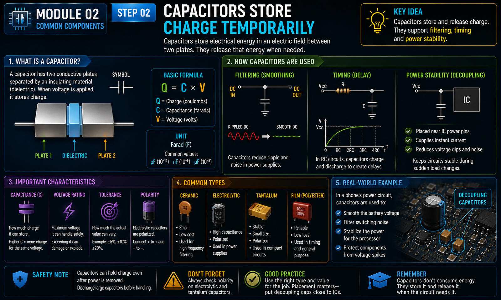
Capacitors support filtering, timing and power stability.
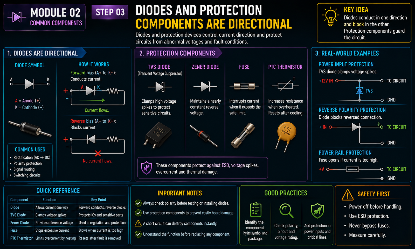
Diodes often conduct differently by polarity. Protection devices can clamp abnormal voltages or interrupt fault current.
This TechForge Academy study PDF is free to download.
DOWNLOAD FREE PDF